Section 7D.12A - 2026 (Jan. & Feb.)
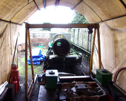
MW2047 Restoration Progress - 2026 (January)
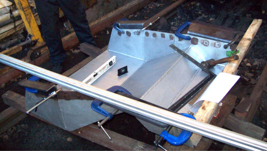

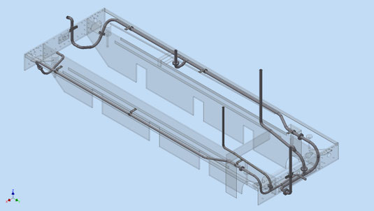
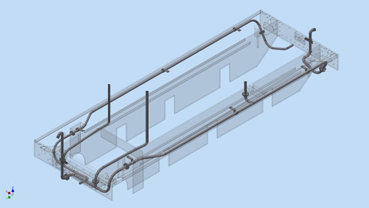
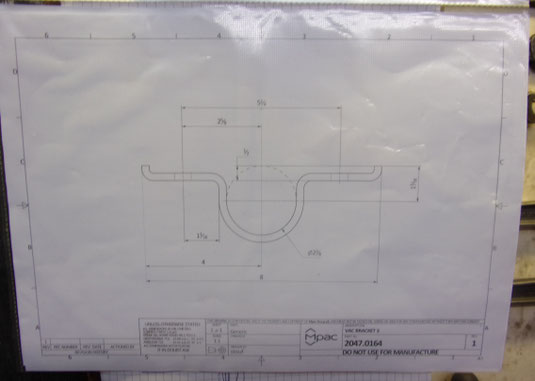
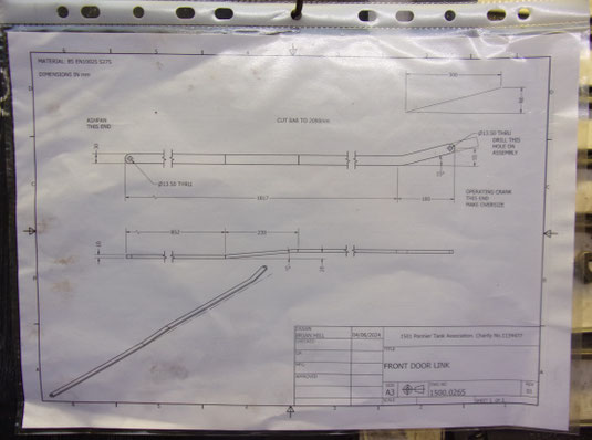
Proposed Pipework Layout for Vacuum Brake
and Steam Heat Systems - Diagram V1 30.1.26
Vacuum pipe on RH (drivers) side and Steam Heat pipe on LH (firemans) side - both mounted under footplate
Brian Hill
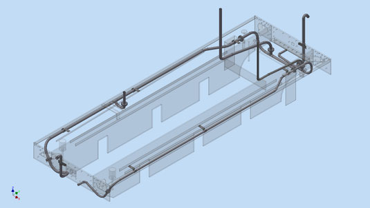
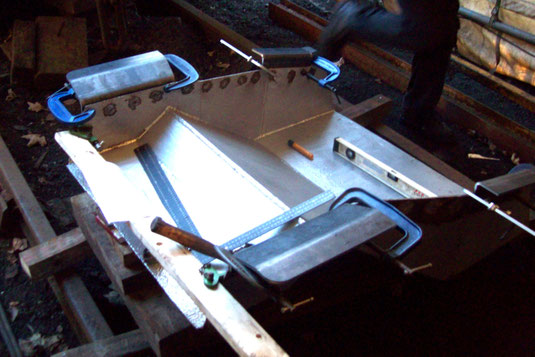
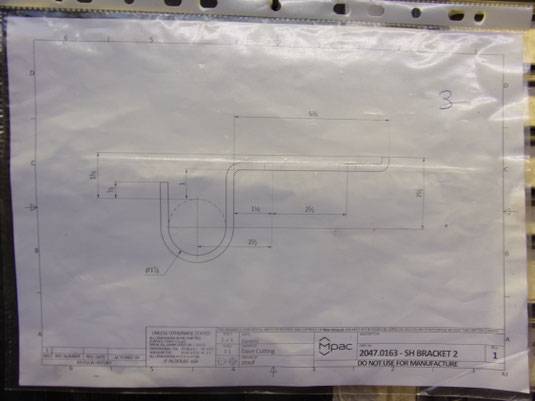
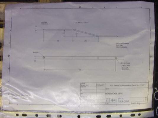
Proposed Pipework Layout for Vacuum Brake
and Steam Heat Systems - Diagram V2 30.1.26
Vacuum pipe on RH (drivers) side and Steam Heat pipe on LH (firemans) side - both mounted under footplate
Brian Hill
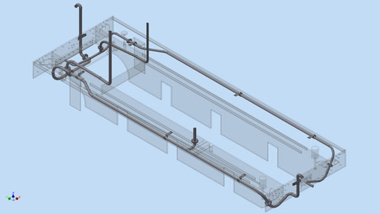
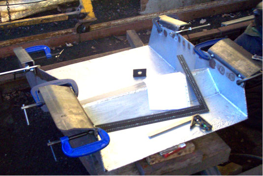
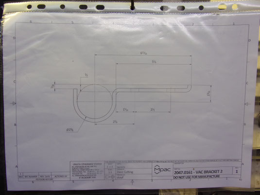
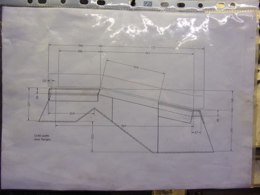
Proposed Pipework Layout for Vacuum Brake
and Steam Heat Systems - Diagram V3 30.1.26
Vacuum pipe on RH (drivers) side and Steam Heat pipe on LH (firemans) side - both mounted under footplate
Brian Hill
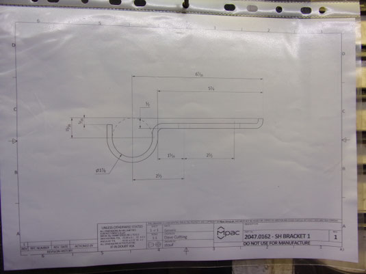
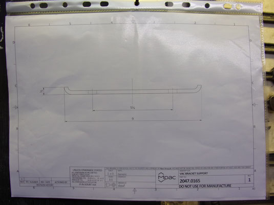
Proposed Pipework Layout for Vacuum Brake
and Steam Heat Systems - Diagram V4 30.1.26
Vacuum pipe on RH (drivers) side and steam Heat pipe on LH (firemans) side - both mounted under footplate
Brian Hill
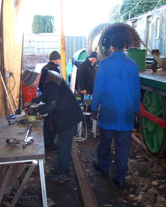
MW2047 Restoration Progress - 2026 (February)
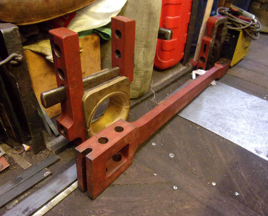
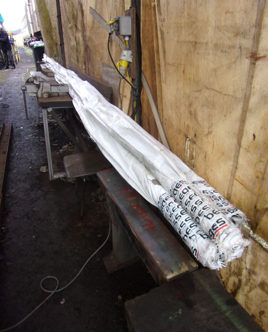
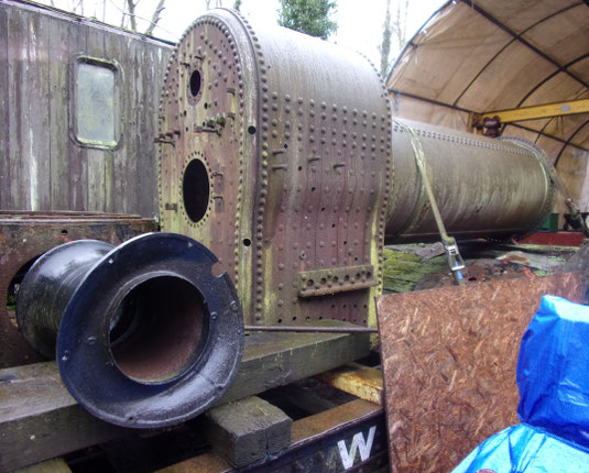
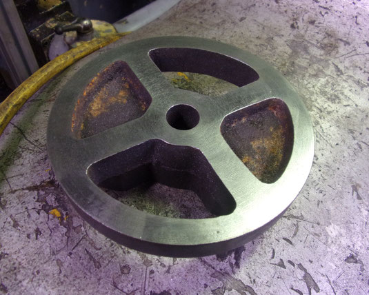

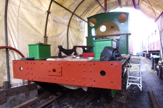
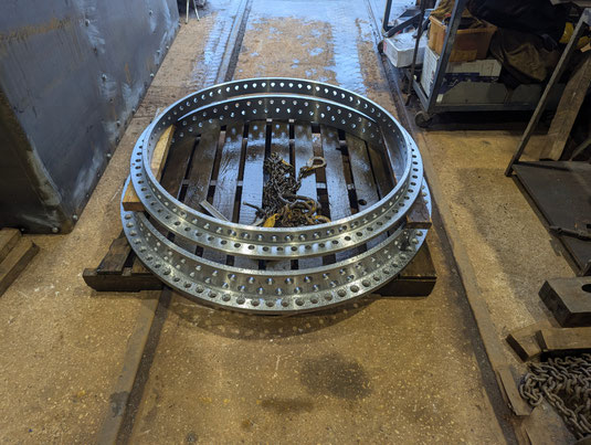
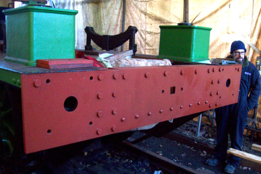
View of front ring (top item) for new boiler
@ Israel Newton on 13.2.26. Bottom item for
SR E1 Class 0-6-0T No.110.
(photo: John Eastwood)